555 Timer Schematic - 555 timer circuit diagrams | different modes of 555 timer / Why to use timer 555?
555 Timer Schematic - 555 timer circuit diagrams | different modes of 555 timer / Why to use timer 555?. May 08, 2021 · the 555 ic timer circuit above shows a very straightforward design where the ic 555 forms the central controlling part of the circuit. 555 timer is an industrial standard ic existing from early days of ic. What is the maximum voltage that can be given to a 555 timer? Jun 21, 2020 · the 4rth circuit diagram shows the standard ic 555 adjustable timer circuit having two sets of timing ranges and an output relay for toggling the desired load. The output voltage from the chip is around 1.5 v lower than vcc when high and around 0 v when low.
Lm555 timer 1 features 3 description the lm555 is a highly stable device for generating 1• direct replacement for se555/ne555 accurate time delays or oscillation. As discussed in the above section, the ic is in its standard monostable mode. What is a 555 timer and how does it work? It was commercialized in 1972 by signetics. Although the schematic looks correct, this basic circuit may actually have a few negative aspects.
The 555-timer circuit design. | Download Scientific Diagram from www.researchgate.net As discussed in the above section, the ic is in its standard monostable mode. The 555 timer is a simple integrated circuit that can be used to make many different electronic circuits. May 08, 2021 · the 555 ic timer circuit above shows a very straightforward design where the ic 555 forms the central controlling part of the circuit. More images for 555 timer schematic » Mar 18, 2017 · simple 555 timer circuits & projects. This pin connects to the negative side of the battery. The output voltage from the chip is around 1.5 v lower than vcc when high and around 0 v when low. 500ms is the same as saying 0.5s so by rearranging the formula above, we get the calculated value for the resistor, r as:
The output voltage from the chip is around 1.5 v lower than vcc when high and around 0 v when low.
Why to use timer 555? Its name is derived from three 5k ohm resistors ,connected in series used in it.the timer ic can produce required waveform accurately. More images for 555 timer schematic » Basic 555 monostable multivibrator circuit. Derivatives provide two (556) or four (558) timing circuits in one package. 555 timer is an industrial standard ic existing from early days of ic. It was commercialized in 1972 by signetics. Additional • timing from microseconds through hours terminals are provided for triggering or resetting if • operates in both astable and monostable modes desired. The 555 timer ic is an integrated circuit (chip) used in a variety of timer, delay, pulse generation, and oscillator applications. The output voltage from the chip is around 1.5 v lower than vcc when high and around 0 v when low. What is the maximum voltage that can be given to a 555 timer? What are different modes of 555 timer? 555 timer helpers schematic the addition of a capacitor to the trigger will not work for short output pulses as there is also a short delay in the recovery of the trigger terminal voltage.
It was commercialized in 1972 by signetics. Referring to the timing diagram in figure 3, a low voltage pulse applied to the trigger input (pin 2) causes the output voltage at pin 3 to go from low to high. This pin connects to the negative side of the battery. Jun 21, 2020 · the 4rth circuit diagram shows the standard ic 555 adjustable timer circuit having two sets of timing ranges and an output relay for toggling the desired load. Why to use timer 555?
The 555-timer circuit design. | Download Scientific Diagram from www.researchgate.net 500ms is the same as saying 0.5s so by rearranging the formula above, we get the calculated value for the resistor, r as: In 2017, it was said over a billion 555 timers are pr. The second 555 timer helper will extend the timers output duration without having to use large values of r1 and/or c1. It was commercialized in 1972 by signetics. Although the schematic looks correct, this basic circuit may actually have a few negative aspects. The output voltage from the chip is around 1.5 v lower than vcc when high and around 0 v when low. What is the maximum voltage that can be given to a 555 timer? 555 timer is an industrial standard ic existing from early days of ic.
555 timer is an industrial standard ic existing from early days of ic.
Jun 04, 2021 · 555 timer pinout. Additional • timing from microseconds through hours terminals are provided for triggering or resetting if • operates in both astable and monostable modes desired. This pin connects to the negative side of the battery. The second 555 timer helper will extend the timers output duration without having to use large values of r1 and/or c1. What is the maximum voltage that can be given to a 555 timer? Although the schematic looks correct, this basic circuit may actually have a few negative aspects. Its name is derived from three 5k ohm resistors ,connected in series used in it.the timer ic can produce required waveform accurately. Once this switch is pushed, the circuit pulls its output to a. 500ms is the same as saying 0.5s so by rearranging the formula above, we get the calculated value for the resistor, r as: What are different modes of 555 timer? More images for 555 timer schematic » As discussed in the above section, the ic is in its standard monostable mode. Mar 18, 2017 · simple 555 timer circuits & projects.
Although the schematic looks correct, this basic circuit may actually have a few negative aspects. May 08, 2021 · the 555 ic timer circuit above shows a very straightforward design where the ic 555 forms the central controlling part of the circuit. The 555 timer ic is an integrated circuit (chip) used in a variety of timer, delay, pulse generation, and oscillator applications. Once this switch is pushed, the circuit pulls its output to a. Lm555 timer 1 features 3 description the lm555 is a highly stable device for generating 1• direct replacement for se555/ne555 accurate time delays or oscillation.
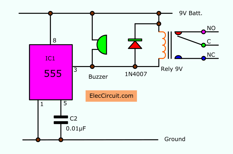
5-30 minuts timer circuit using IC 555 from www.eleccircuit.com With this information you will learn how how the 555 works and will have the experience to build some of the circuits below. More images for 555 timer schematic » 555 timer helpers schematic the addition of a capacitor to the trigger will not work for short output pulses as there is also a short delay in the recovery of the trigger terminal voltage. Why to use timer 555? Once this switch is pushed, the circuit pulls its output to a. Mar 18, 2017 · simple 555 timer circuits & projects. A monostable 555 timer is required to produce a time delay within a circuit. It was commercialized in 1972 by signetics.
A monostable 555 timer is required to produce a time delay within a circuit.
As discussed in the above section, the ic is in its standard monostable mode. Lm555 timer 1 features 3 description the lm555 is a highly stable device for generating 1• direct replacement for se555/ne555 accurate time delays or oscillation. 555 timer was first introduced by signetics corporation in 1971 as se555/ne555. Its name is derived from three 5k ohm resistors ,connected in series used in it.the timer ic can produce required waveform accurately. If a 10uf timing capacitor is used, calculate the value of the resistor required to produce a minimum output time delay of 500ms. Mar 18, 2017 · simple 555 timer circuits & projects. Once this switch is pushed, the circuit pulls its output to a. Although the schematic looks correct, this basic circuit may actually have a few negative aspects. In 2017, it was said over a billion 555 timers are pr. Jun 21, 2020 · the 4rth circuit diagram shows the standard ic 555 adjustable timer circuit having two sets of timing ranges and an output relay for toggling the desired load. Derivatives provide two (556) or four (558) timing circuits in one package. 555 timer is an industrial standard ic existing from early days of ic. It was commercialized in 1972 by signetics.


Posting Komentar
Posting Komentar